Cloud Design Document
1. AWS Container Platform
1.1 Summary
The architecture we are targeting, seamlessly accommodates the cloud hosted application while focusing on container-based cloud native applications.
Containers are a solution to the problem of how to get software to run reliably when moved from one computing environment to another. A container consists of an entire runtime environment: an application, plus all its dependencies, libraries and other binaries, and configuration files needed to run it, bundled into one package. By containerizing the application platform and its dependencies, differences in OS distributions and underlying infrastructure are abstracted away.
When deploying or migrating applications on/to containers, there comes the responsibility to manage the lifecycles of containers, especially in large, dynamic environments. Hence container orchestration is used for below tasks:
- Redundancy and availability of containers
- Provisioning and deployment of containers
- Scaling up or removing containers to spread application load evenly across host infrastructure
- Movement of containers from one host to another if there is a shortage of resources in a host, or if a host dies
- Allocation of resources between containers
- External exposure of services running in a container with the outside world
- Load balancing of service discovery between containers
- Health monitoring of containers and hosts
- Configuration of an application in relation to the containers running it.
Containers are deployed onto hosts, usually in replicated groups. When it’s time to deploy a new container into a cluster, the container orchestration tool schedules the deployment and looks for the most appropriate host to place the container based on predefined constraints. Once the container is running on the host, the orchestration tool manages its lifecycle according to the specifications in the container’s definition file.
The beauty of container orchestration tools is that you can use them in any environment in which you can run containers. Moreover containers are supported in just about any kind of environment, from traditional on-premise servers to public cloud instances running in Amazon Web Services (AWS), Google Cloud Platform (GCP), or Microsoft Azure.
When it comes to container management platforms, Amazon Elastic Kubernetes Service (Amazon EKS) is an easy way to run containerized applications on Kubernetes on the Amazon Web Services (AWS) Cloud.
1.1.1. Cloud Native – Container based Applications
This design creates capabilities by supporting container-based applications using EKS. Amazon Elastic Kubernetes Service (Amazon EKS) is a fully managed Kubernetes service. EKS clusters can use AWS Fargate, which is serverless compute for containers. Fargate removes the need to provision and manage servers, allows to pay for resources per application, and improves security through application isolation by design. Moreover, EKS is deeply integrated with services such as Amazon CloudWatch, Auto Scaling Groups, AWS Identity and Access Management (IAM), and Amazon Virtual Private Cloud (VPC), providing you a seamless experience to monitor, scale, and load-balance your applications. Additionally, EKS provides a scalable and highly-available control plane that runs across multiple availability zones to eliminate a single point of failure.
You can also easily migrate any standard Kubernetes application to EKS without needing to refactor your code.
1.1.2. Architecture
This document defines the Architecture elements and aspects. Some key elements of the Architecture are:
- Everything is a code, all deployments, updates, management will be using Infrastructure as Code (IaC).
- Network Zoning and connectivity based on standard protocols and Cloud services.
- Strict segregation of shared services tier as well as application tiers.
- Highly automated environment using a continuous integration and continuous deployment pipelines.
- Amazon container service (EKS) using AWS container registry (ECR) for docker images.
- Identity management services primarily using AWS IAM which later on will be deployed fully based on federation services and claims-based access control.
- IT Governance for a dynamic and secure environment.
- A highly available architecture that spans two Availability Zones.
- In the public subnets, managed NAT gateways to allow outbound internet access for resources in the private subnets.
- In one public subnet, a Linux bastion host in an Auto Scaling group to allow inbound Secure Shell (SSH) access to Amazon Elastic Compute Cloud (Amazon EC2) instances in private subnets. The bastion host is also configured with the Kubernetes kubectl command line interface for managing the Kubernetes cluster.
- An Amazon EKS cluster, which provides the Kubernetes control plane.
- In the private subnets, a group of Kubernetes nodes

Figure 1 Architecture Diagram
1.2 Scope
It has been decided to utilize AWS as the primary Cloud service provider and hence, most of the architecture and design is focused on services specific to AWS.
Elastic Kubernetes service(EKS) will be used for setting up cluster which will be used to setup containers that will have applications deployed. According to the requirement we can use load balancer or autoscaling groups which will be needed in real time scenarios. Container images will be stored in Elastic Container Registry(ECR).EC2 based cluster will be used primarily, setup can be later on configured with Fargate based EKS cluster if required.
Primarily the required infrastructure architecture can be tested with stateless application, eventually the changes can be made to accommodate the stateful applications.Rolling deployment strategy will be used for deployment on kubernetes nodes.
Terraform will be used to deploy required infrastructure and Azure devops for deployments.
2. Principles
The integrated Cloud architecture provides guidance based on principles. Whenever a choice is to be made how to implement or change a functionality or service, it will be challenged and verified against these principles. Thereby ensuring the IT environment adheres to chosen standards, evolves in the desired direction and avoids unnecessary complexity.
This chapter summarizes the key principles that guides the choices and implementation of the Client AWS Target Architecture environment as implemented and maintained by Sogeti.
These principles are challenged by the specific characteristics of applications and the required service levels, especially in the transition architecture. Therefore, these principals must be interpreted as guidelines for making the right, future proof, choices.
2.1. Sogeti
Sogeti defines several principles underlying the integrated Cloud architecture & design our best-practices and Cloud vendor guidelines.
First the founding principles are defined:
- “SaaS before PaaS, before IaaS”.
- Public Cloud before Private Cloud.
- “Everything is a Service”.
- All applications and services are self-contained and “loosely coupled” with any interfaces based on internet routable protocols and specifically defined interfaces and dataflows.
- Standard Cloud facilities and services will be used to its fullest with no or minimal customization, maximizing efficiency.
- “The Unreliable Cloud”: Failure of any Cloud environment or service must be designed in the solution.
- “Destroy & Redeploy”: Every application or service in the Cloud environment must be re-creatable by means of standard services: redeploy and restore.
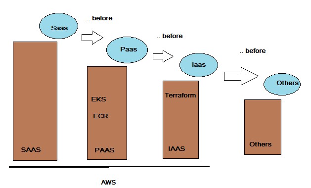
Figure 2 Basic Cloud Strategy
Additional platform and application specific principles:
- Amazon public Cloud (AWS) is the primary target environment for all applications and management agents. Azure is positioned as second option to the architectural standard and does contain existing set of applications.
- Applications and service components must be stateless and re-startable for simplified availability, deployment and recovery to adhere to the “destroy & redeploy” principle.
- Systems, middleware components and applications must be automatically re-deployable to facilitate recovery, minimize operational costs and maximize quality and reproducibility.
- The Sogeti-managed Cloud environment(s) for the applications provide authorization services for access to and within the applications.
- Applications should be Claims-aware to support standardized, federation-based, access control at application level.
- Every instance of a docker, server or system will have only one role in the infrastructure, thereby minimizing complexity, maintenance and enhancing security.
In the context of the Sogeti Cloud Design, an Application is loosely defined as the whole of files and settings that make up the runtime, all included libraries and middleware components (not being part of the default available Cloud environment), configuration files, databases configuration and structure of databases accessed directly by the application, environment configuration (but not the actual environment like the OS or disks), deployment scripts, templates and/or runbooks, application specific B&R settings and Monitoring settings, AWS (Cloud) services configuration required for the application environment (like EBS, EC2, and DirectConnect and VPC definitions), and finally the exposed interfaces. SaaS in this document is referred with the context of 3rd Party application which are not hosted on Client’s AWS cloud platform whereas any such application hosted on the Client’s AWS cloud platform are referred as Packaged software. SaaS in this document does not refer to SaaS based tooling.
3. Technology
3.1 Overview of Target Architecture
Due to the rapidly changing Cloud technologies and the focus on application transition to the Cloud, AWS service updates will be adapted when needed and feasible to the changing Cloud services. To make this useable and manageable, patterns and variants are defined to standardize the available services and the way they are used by applications and other services.
3.1.1. AWS Account Structure
This view shows the AWS Account Structure for on AWS :
Primary Region : EU-WEST-1(Ireland) DR Region: EU-CENTRAL-1(Frankfurt)
PRODUCTION VPC:
- All Production releases for Client applications will be hosted on this VPC.
- Application stacks will be hosted in HA (Only when required by application)
TEST VPC:
- All Acceptance releases for Client applications will be hosted on this VPC.
DEV VPC:
- All Development tasks for Client applications will be hosted on this VPC.
3.1.2. Technical Overview
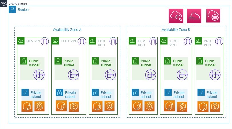
Figure 3 Technical Overview of Target Architecture
| Design Decision(s) | |
|---|---|
| DD-TA-01 | Design needs to be Cost effective. |
| Rationale | All new project need to be based on saving costs in short term. |
| DD-TA-02 | All VPC’s have internet gateway and NAT. |
| Rationale | To simplify the network yet secure it. |
| DD-TA-03 | Each Application Environment (Dev,Test,Production) has its individual VPC. |
| Rationale | Each Environment is segregated into it’s own VPC for ease of network management and application connectivity. |
| DD-TA-04 | Mature IAM configuration and fine grained set of security mechanisms. |
| Rationale | As all the application are within single VPC, there is a risk to reduce the blast radius. This risk is mitigated by IAM permissions, security group and NACLs given at granular level perhaps using tags. |
| DD-TA-5 | Only public endpoints are exposed to the public subnet of the environment. Rest of the services are contained in the private subnet. |
| Rationale | This is one of the best practices defined by AWS and also adopted by Sogeti. |
| DD-TA-6 | Critical components and services within environment are in Multiple AZ’s. |
| Rationale | To provision these components in High Availability setup, Multi AZ’s is used in AWS. All acceptance and production environments will have minimum of 2 AZ’s, More than 2 AZ deployment can be justified by proposing a valid business case. |
| DD-TA-7 | Each application cell is secured with security groups. Inter tier communication is allowed by referencing each security group. |
| Rationale | Security groups are used to secure the inter application communication by blocking communication with other application within the same tier. |
3.2 Patterns and variants
The below table will define the patterns and variants that will be used to realize the Landing Zone on AWS.
3.2 Patterns and variants
The below table will define the patterns and variants that will be used to realize the Landing Zone on AWS.
| Pattern | Variants |
|---|---|
| Naming standard. | Client Tagging and Naming Standards for AWS |
| Provisioning. | Terraform |
| Backup/Restore. | AMI, S3, Snapshots. |
| I&AM. | AWS Managed AD, AWS IAM. |
| Platform. | Containers,EKS |
| Monitoring Pattern. | CloudWatch Monitoring |
| Logging. | AWS CloudWatch, AWS Cloudtrail. |
| Security & Compliance. | AWS GuardDuty, AWS Config, AWS Trusted Advisor. |
| CICD. | Azure Devops |
| AMI Repository. | Baseline using AWS System Manager. |
| Container Registry. | AWS ECR |
| Patch Management. | AWS System Manager. |
3.2.1. Cloud Platform Standards – AWS
AWS will be the preferred vendor for cloud related services.
| DD-CS-8 | Primary AWS region: eu-west-1 (Ireland) Secondary AWS region: eu-central-1 (Frankfurt). |
| Rationale | Ireland is better in terms of costs and newer services. |
| DD-CS-9 | Infrastructure as Code (IaC) will be the primary mode of operation. |
| Rationale | IaC helps to deploy infrastructure in repeatable and consistent manner. |
| DD-CS-10 | Terraform will be the used as primary choice for deployment of IaC. |
| Rationale | Terraform has some added benefits over Cloudformation eg, performing custom tasks, managing misaligned state, etcetera. |
3.2.1. Tagging and Naming Conventions
An important aspect of every environment is the standards applied for naming all the different resources, especially for dynamic environments like the Cloud. The naming conventions define standards for every type of resource in the environment, from Cloud services to Virtual Machines. Please refer to the following documents for more details:
- Principle Naming Services 1.1
The naming conventions are based on the following guidelines:
- Any name must be unique: Any name must be unique within the Client landscape and subscription for objects of the same type. For example, although technically possible, it is not allowed to have two VM’s with the same name in two different VPC’s.
- Use of characters: Names must start with a letter or number and can contain only letters, numbers and dashes.
- Writing the name: All names are in lower case.
- No use of spaces: Spaces are to be avoided where possible.
- Name lifespan: A name shouldn’t be changed! If the object get’s a new function or is being used for a different BU it either keeps the name or it has to be added with a secondary tag with the correct name.
- Names do not contain a function: It’s not allowed to use a function in a name. This can cause confusion and makes it easy to do assumptions. For example: “databaseserver1” should not be allowed.
- Names must support the automation tooling: To deploy and manage the environments, automation tools must be used, all name created must be supported by the tool.
- Costs Tags: To track the costs on detailed level, cost tags needs to be added and activated. These tags can represent business categories (such as cost centers, application names, or owners) to organize costs across business units like mail/parcel/cbs.
3.2.3. Tools
Specific set of tools is defined to run and maintain the Cloud environment. Terraform is the primary tool to deliver AWS services and resources. Additional tools includes the likes of AWS cli, powershell tools and versioning tools. Purpose of this is to standardize the way the environment is managed and maintained. More tools may be required depending on the type of application.
Sogeti suggests to perform tool selection PoC to check the feasibility as per the use case.
3.3 Management
3.3.1. Configuration and Asset Management
Due to the nature of the application infrastructure portfolio within the scope of the cloud environment, two types of Configuration Management (CM) are needed, which are related from a deployment point of view, but not the same. The design decisions that direct configuration management are:
- Operational Configuration & Asset Management.
The design describes the tool to monitor the target architecture environment is AWS Cloudwatch
| Design Decision(s) | |
|---|---|
| DD-CM-11 | Configuration management is based on ‘Desired State’ configuration and control. |
| Rationale | Modern automated provisioning is based on Cloud services API’s that can identify state and act accordingly. Terraform is used for AWS. |
| DD-CM-12 | Operational Asset Management is done outside the scope of the cloud provided configuration services. |
| Rationale | To ensure unauthorized changes can be detected, a single truth must be maintained on asset level. Additional mechanism like tag enforcement, Aws Config is used to ensure compliance and appropriate governance. |
| DD-CM-13 | Parameters for provisioning are delivered by the application package or defined at Cloud environment level. |
| Rationale | Whenever possible applications should define their ‘surroundings’ and dependencies. Only environment specific parameters should be defined elsewhere. AWS Parameter store is used to define and store these parameters |
Monitoring is divided in the following levels.
- Level 1: Infrastructure monitoring.
- Level 2: Application monitoring.
AWS – Amazon Web Services will be responsible in the stack as per the shared responsibility model https://aws.amazon.com/compliance/shared-responsibility-model/
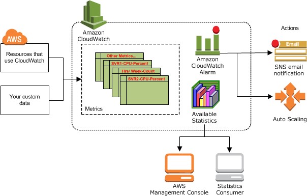
Figure 4 Cloudwatch overview
Amazon EKS control plane logging provides audit and diagnostic logs directly from the Amazon EKS control plane to CloudWatch Logs in your account. These logs make it easy for you to secure and run your clusters. You can select the exact log types you need, and logs are sent as log streams to a group for each Amazon EKS cluster in CloudWatch..
AWS CloudTrail: Amazon EKS is integrated with AWS CloudTrail, a service that provides a record of actions taken by a user, role, or an AWS service in Amazon EKS. CloudTrail captures all API calls for Amazon EKS as events. The calls captured include calls from the Amazon EKS console and code calls to the Amazon EKS API operations.All Cloudtrail logs are places in a central S3 bucket which has restricted access. These Cloudtrail logs are fed into Athena which is visualized in AWS Quicksight.
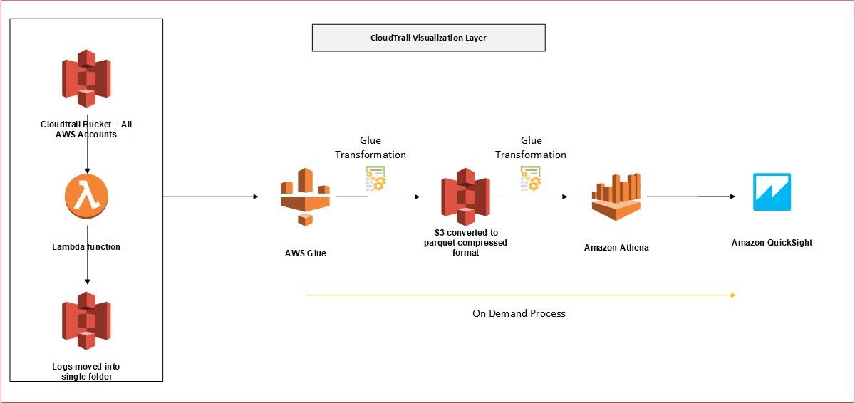
Figure 5 Cloudtrail visualization layer
| Design Decision(s) | |
|---|---|
| DD-ML-14 | Applications will log to their default location. |
| Rationale | Deviation from the standard locations will incur additional complexity while not providing any tangible benefit. |
| DD-ML-15 | Automations will regularly clean up the logs that are past the retention period. |
| Rationale | Logging must be extensive and can accumulate to large volumes. Therefore regular clean-up is required to prevent getting over a threshold. |
| DD-ML-16 | Metric data will be collected at 5 min interval using AWS CloudWatch. |
| Rationale | 5 min polling is the default cloudwatch setting. For cost optimization, advanced monitoring is used only when there is a specific requirement. |
| DD-ML-17 | CloudWatch logs will be retained for 1month. |
| Rationale | One month period will be enough to perform operational maintenance and the logs will be moved to archive for later retrieval. Dashboards are in LogicMonitor. |
| DD-ML-18 | Access to all logs have restricted access. |
| Rationale | Access is granted only to specific functional roles. |
| DD-ML-19 | CloudTrail is enabled in all AWS accounts. |
| Rationale | To have governance and audit log of the entire environment |
| DD-ML-20 | CloudTrail logs is collected centrally |
| Rationale | For security and ease of management. |
3.3.2. Provisioning
Enterprises everyday face the challenge of rapidly changing landscape, evolving security requirements and performance scalability. Applications need to support regular updates, upgrades and fixes, which are almost impossible with legacy approach. The new and modern approach is to release, test and redeploy changes more often. This is achieved using continuous integration and continuous delivery pipelines. This design describes AWS native tools for incorporating CICD mechanism for the Target architecture for rapid feature development and operational stability.
The target architecture is provisioned with Infrastructure as Code - Terraform Based environments are all deployed using the Azure Devops. AWS ECR is the central code repository for the entire Client environment to store container images.
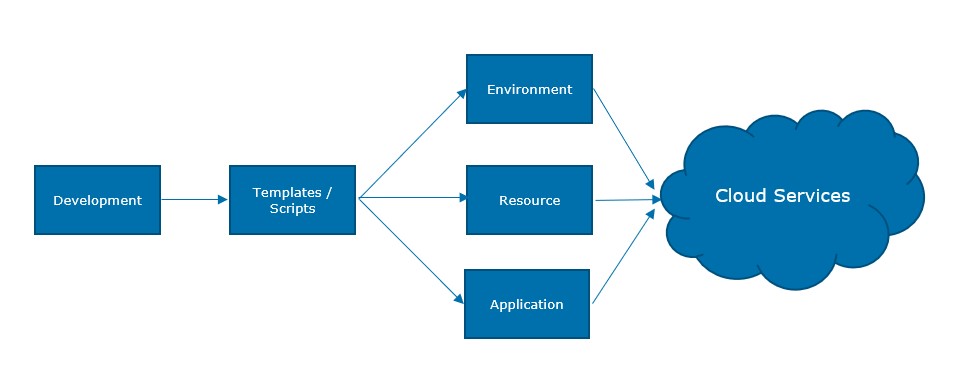
Figure 6 Provisioning Flow
There are ways for deployment: fully or semi-automated based on images and templates with configuration and customization. Deployment in the Cloud is focused on providing the optimal flexibility of the Cloud through Continuous Deployment in a DevOps flow. This requires the use of automation and templates to its fullest to ensure repeatability, availability and security.
3.3.3. Capacity Management
There are several types of Kubernetes autoscaling supported in Amazon EKS:
Cluster Autoscaler — The Kubernetes Cluster Autoscaler automatically adjusts the number of nodes in your cluster when pods fail to launch due to lack of resources or when nodes in the cluster are underutilized and their pods can be rescheduled on to other nodes in the cluster.
Horizontal Pod Autoscaler — The Kubernetes Horizontal Pod Autoscaler automatically scales the number of pods in a deployment, replication controller, or replica set based on that resource’s CPU utilization.
Vertical Pod Autoscaler — The Kubernetes Vertical Pod Autoscaler automatically adjusts the CPU and memory reservations for your pods to help “right size” your applications. This can help you to better use your cluster resources and free up CPU and memory for other pods.
AWS RDS (PaaS databases) start/stop is used to temporarily change the state of the database to save money. This is generally used for Dev/Test and Acceptance environment which do not need to be on all the time. This process is automated using appropriate tagging strategy.
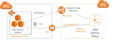
Figure 7 EKS Flow
3.3.4. Patching
Amazon EKS runs Kubernetes control plane instances across multiple Availability Zone to ensure high availability. Amazon EKS automatically detects and replaces unhealthy control plane instances, and it provides automated version upgrades and patching for them.
3.3.5. Backup and Restore
Amazon EKS runs Kubernetes control plane instances across multiple Availability Zone to ensure high availability. Amazon EKS automatically detects and replaces unhealthy control plane instances, and it provides automated version upgrades and patching for them.
This control plane consists of at least two API server nodes and three etcd nodes that run across three Availability Zones within a Region. Amazon EKS automatically detects and replaces unhealthy control plane instances, restarting them across the Availability Zones within the Region as needed.
Disaster: Disaster recovery protects the environment from Region’ failures that seriously degrades service availability of an Availability Zone/Region (AWS). Amazon EKS leverages the architecture of AWS Regions in order to maintain high availability. | Design Decision(s) | | |——————–|—————————————————————————————————————————————————————————-| | DD-BR-21 | Backup of RDS Databases is done with automated RDS snapshots, Backup of other EC2 block storage is done with Data lifecycle management. S3 using S3 replication | | Rationale | Use of Cloud-native services ensures lower complexity and management.Cost reduction is achieved by using lifecycle policies and data is moved to Glacier. |
3.3.6. Access Management
All users must be authenticated (signed in to AWS) as the AWS account root user, an IAM user, or by assuming an IAM role. Also company’s single sign-on authentication can be used. In these cases, administrator will set up identity federation using IAM roles. When accessing AWS using credentials from another company, user will be assuming a role indirectly.
3.4. Cloud Network
Following network architecture will be used for EKS Cluster:
This VPC has two public and two private subnets. One public and one private subnet are deployed to the same Availability Zone. The other public and private subnets are deployed to a second Availability Zone in the same Region. We recommend this option for all production deployments. This option allows you to deploy your worker nodes to private subnets and allows Kubernetes to deploy load balancers to the public subnets that can load balance traffic to pods running on worker nodes in the private subnets.
Public IP addresses are automatically assigned to resources deployed to one of the public subnets, but public IP addresses are not assigned to any resources deployed to the private subnets. The worker nodes in private subnets can communicate with the cluster and other AWS services, and pods can communicate outbound to the internet through a NAT gateway that is deployed in each Availability Zone. A security group is deployed that denies all inbound traffic and allows all outbound traffic. The subnets are tagged so that Kubernetes is able to deploy load balancers to them.
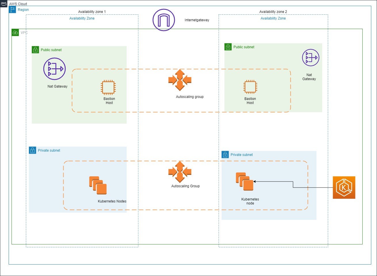
Figure 8 Cloud Network Diagram
3.5. Identity And Access Management
Identity stores that can be used include AWS Managed AD and AzureAD for certain management accounts.
Primarily IAM Users, Groups and Roles can be used to manage users. An IAM administrator can use policies to specify who has access to AWS resources, and what actions they can perform on those resources. Every IAM entity (user or role) starts with no permissions. To give a user permission to do something, an administrator must attach a permissions policy to a user. Or the administrator can add the user to a group that has the intended permissions. When an administrator gives permissions to a group, all users in that group are granted those permissions.
EKS cluster is managed as follows using service based IAM roles:
- Kubernetes clusters managed by Amazon EKS make calls to other AWS services on your behalf to manage the resources that you use with the service.
- The Amazon EKS worker node kubelet daemon makes calls to AWS APIs on your behalf. Worker nodes receive permissions for these API calls through an IAM instance profile and associated policies.
When IAM roles are used for service accounts for a pod, the containers in the pod have all permissions assigned to the service account and the worker node IAM role.
*3.5.1. Authentication and Authorization**
The authentication services provide the interfaces required to authenticate users (both internal and external) against a designated Identity Provider (Enterprise, External or Customer).
Primarily IAM authentication service can be used. AWS MFA, a security feature available will be used as a security measure. MFA requires users to prove physical possession of a hardware MFA token or MFA-enabled mobile device by providing a valid MFA code.
Later on IAM can be used to grant your employees and applications federated access to the AWS Management Console and AWS service APIs, using your existing identity systems such as Microsoft Active Directory.
Authorization carries out the rest of an organization’s identity and access management processes once the user has been authenticated. Users are granted authorizations according to their role at an organization.IAM policies will be used to restrict access at granular level.
The following design decisions have been made for the authentication services Building Block.
| Design Decision(s) | |
|---|---|
| DD-AUTHN-01 | Leverage self-registration functionality provided by the identity provider as much as possible. |
| Rationale | Enables self-service capabilities like password reset, MFA and registration at the IDaaS provider. |
| DD-AUTHN-02 | Credentials rotation to prevent unauthorized access |
| Rationale | Mandate AWS keys and password rotation every 15 days. |
3.5.2. AWS IAM
Users: An AWS IAM user is an entity that represents a person or application that uses it to interact with AWS. A user in AWS consists of a name and credentials. IAM user consists of a username and password while credentials consists of AWS secret and access key. IAM user can have access console using username and password while AWS CLI access requires the secret and access keys. The AWS account root user is not the same user as an IAM user with full administrator privileges.
Groups: An IAM group is a collection of IAM users. Groups allows to specify permissions for multiple users, which can make it easier to manage the permissions for those users. For example, we could have a group called Admins and give that group the types of permissions that administrators typically need. Any user in that group automatically has the permissions that are assigned to the group. If a new user joins the organization and needs administrator privileges, we can assign the appropriate permissions by adding the user to that group. Similarly, if a person changes jobs in the organization, instead of editing that user’s permissions, we can remove him or her from the old groups and add him or her to the appropriate new groups.
Policies: Access to AWS resources is granted by creating policies and attaching them to IAM identities (users, groups of users, or roles) or AWS resources. A policy is an object in AWS that, when associated with an identity or resource, defines their permissions. AWS evaluates these policies when a principal entity (user or role) makes a request. Permissions in the policies determine whether the request is allowed or denied. Most policies are stored in AWS as JSON documents. AWS supports six types of policies: identity-based policies, resource-based policies, permissions boundaries, Organizations SCPs, ACLs, and session policies.
Roles: AWS IAM roles can explained in the following categories:
Service Roles: A role that a AWS service assumes to perform actions in the account on your behalf is known as service role. This type of role is used when we set up some AWS service environments, we must define a role for the service to assume. This service role must include all the permissions required for the service to access the AWS resources that it needs. Service roles vary from service to service. Service roles provide access only within your account and cannot be used to grant access to services in other accounts. You can create, modify, and delete a service role from within IAM.
Service Linked Roles: A unique type of service role that is linked directly to an AWS service. Service-linked roles are predefined by the service and include all the permissions that the service requires to call other AWS services. The linked service also defines how we create, modify, and delete a service-linked role. A service might automatically create or delete the role. It might allow us to create, modify, or delete the role as part of a wizard or process in the service. Or it might require that we use IAM to create or delete the role. Regardless of the method, service-linked roles make setting up a service easier because we don’t have to manually add the necessary permissions.
Federated User Role: Instead of creating an IAM user, we can use existing identities from Azure AD. These are known as federated users. AWS assigns a role to a federated user when access is requested through an identity provider.
3.6 Platform
The platform section defines the container platform, image management, AMI management and docker registry. These are only some of the topics of the platform section. These topics have been dived into deeper for better explanation, however platform section is not limited to only these services.
3.6.1. Elastic Kubernetes Service
Containers wrap up software in a complete file system that contains everything it needs to run: code, runtime, system tools and system libraries. This guarantees that it will always run the same, regardless of the environment it is running in and completely isolated from each other.
Containers provides an additional layer of abstraction and automation of operating-system-level virtualization on Windows and Linux. Containers use the resource isolation features of the Windows or Linux kernel to allow independent “containers” to run within a single instance, avoiding the overhead of starting and maintaining virtual machines. Starting up containers take seconds instead of minutes and run completely in memory.
As containers run independent from the infrastructure they use, containers can be (automatically) managed by Developers and Testers without the intervention required from operational support teams. This platform independence also promotes an effective non production to production pipeline.
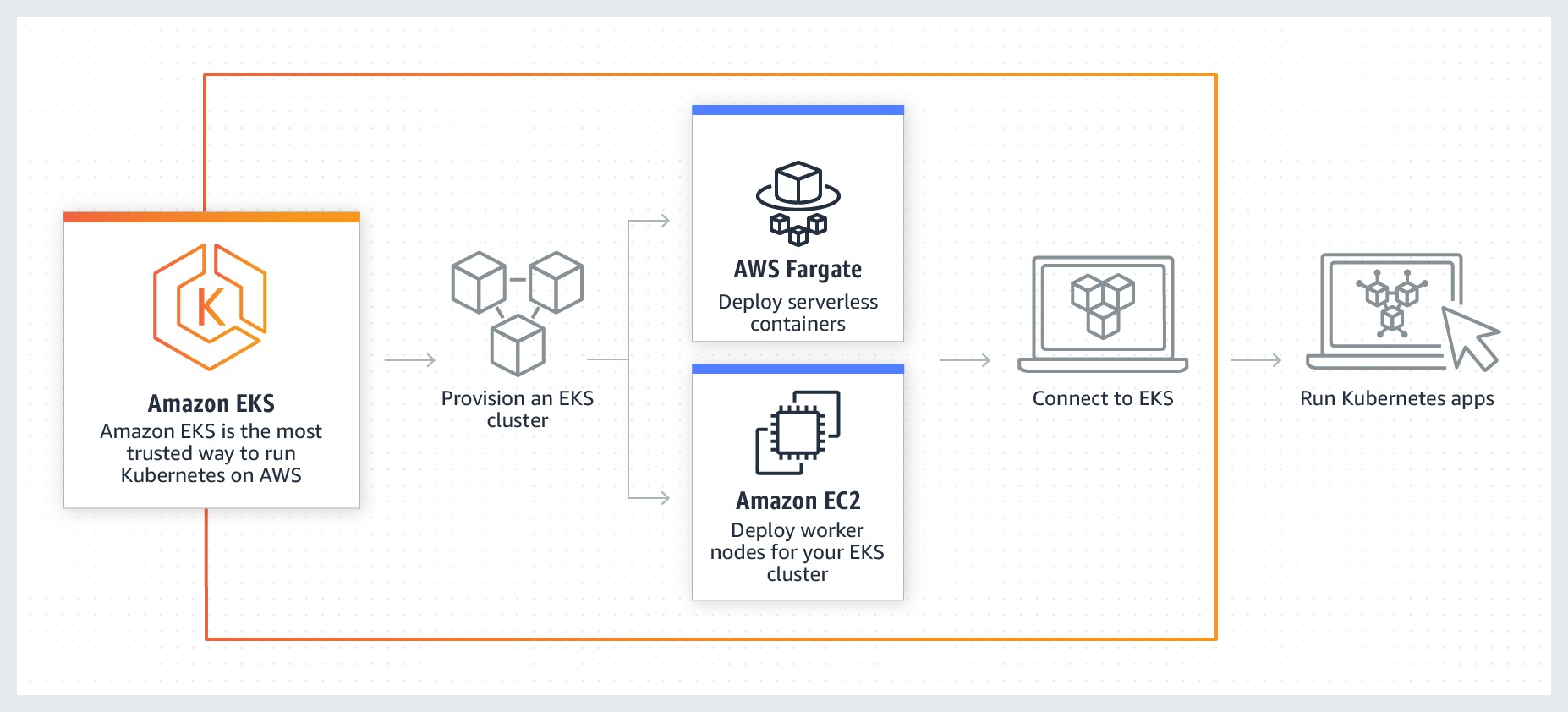
Figure 9 Cloud Native – Containers | EKS Workflow
| Design Decision(s) | |
|---|---|
| DD-PL-21 | Containers can be used together with runbook automation tools to accelerate the CICD pipelines and to give developers more flexibility and autonomy. |
| Rationale | Containers are widely adopted in the DevOps world to accelerate agile development. Ansible is seen as the most popular tool to automate deployment of Linux containers. |
| DD-PL-22 | Separate container clusters will be created per environment. |
| Rationale | It is best practice to create separate container services for production and Non Production containers to create separation of duties (RBAC). |
| DD-PL-23 | Separate container clusters will be created per application group. |
| Rationale | It is best practice to create separate clusters for every different application stack with does not primarily share data within an environment (Prod and Non Prod). Sogeti suggests separate VPC incase of application for a different Business Unit (Mail, Parcels, CBS). |
| DD-PL-24 | Developers are allowed to create their own containers on the Non Prod environments but not on the production environment. |
| Rationale | Changes to production should be done using proper release management and preferably not be executed by Developers. |
3.6.2. Container Registry
Container images are typically stored in a registry that can either be accessible by the public registry or set up with limited access for a small set of users. Public registries such a Docker Hub will be used to get started with the docker images. Images contains just layers. Using private registry allows Client to be in full control of the images that flow into the environment. Selecting AWS ECR provides benefits of performance, secured workflow with tight integration with AWS IAM.
One of the final steps of the pipeline involves building the container images that will be pulled and executed in our environment.
3.7 CICD
3.7.1. Overview
Continuous Integration and Continuous Delivery is a practice to deliver the code quickly to generate business value. This section is a sub part of the section [Provisioning] where the design decisions are described.
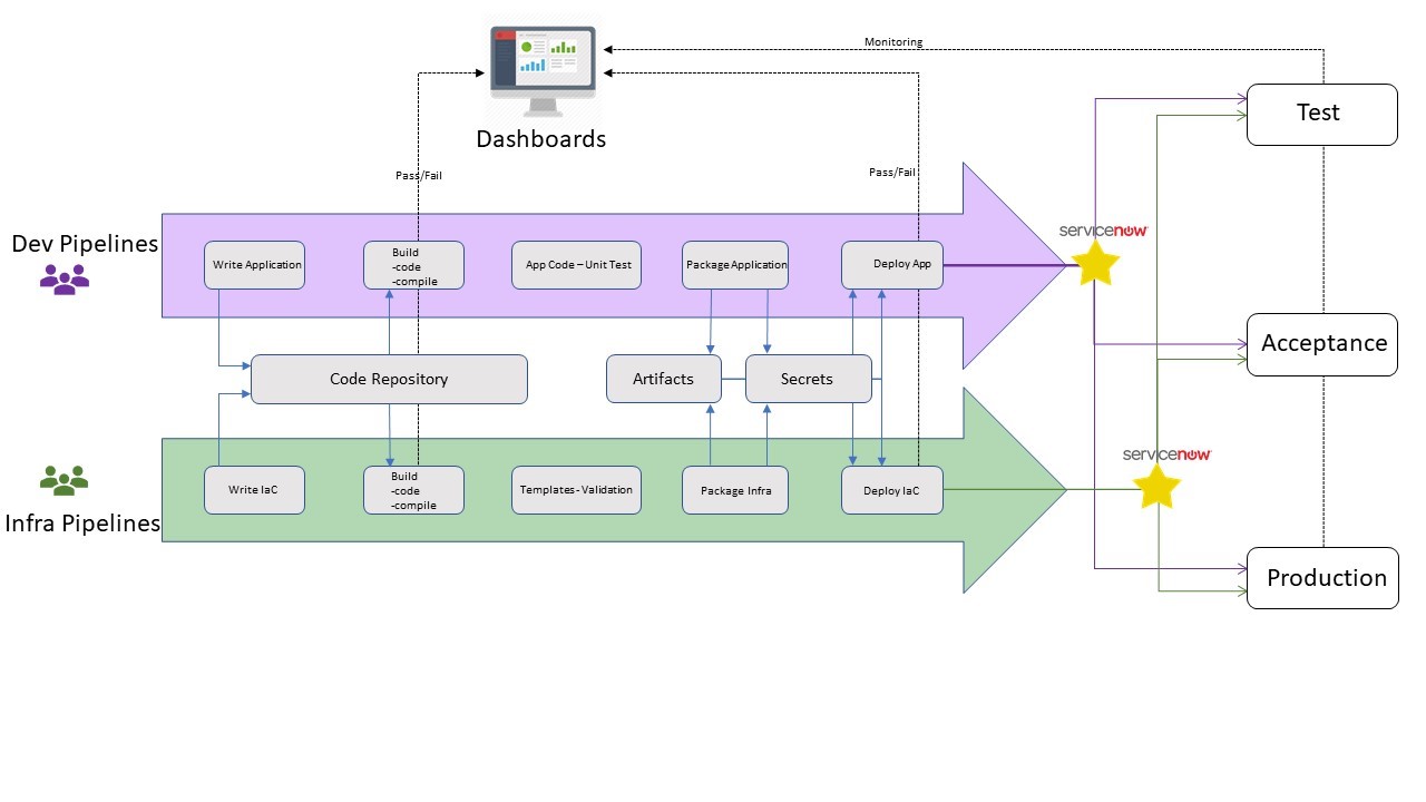
Figure 10 Functional view of Infra and Dev Pipelines
The Azure DevOps Project simplifies the setup of an entire continuous integration (CI) and continuous delivery (CD) pipeline with Azure DevOps.
DevOps Projects does all the work for the initial configuration of a DevOps pipeline including everything from setting up the initial Git repository, configuring the CI/CD pipeline, creating an Application Insights resource for monitoring, and providing a single view of the entire solution with the creation of a DevOps Projects dashboard in the Azure portal.
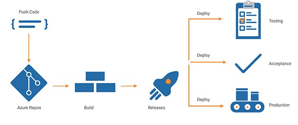
Figure 11 Azure Devops CICD
Below are the various patterns for deployment and update management of the applications: The context of the deployment pattern is based on the Container environment usin Azuredevops.
Selection of a deployment patterns is based on application type, business service level, feasibility, etcetera. This however is out of scope of this document and is not explained herewith.
3.7.2. Rolling Deployments
With rolling updates, the entire fleet of servers is divided into portions so that the entire fleet isn’t updated at once. During this deployment, there are 2 versions of the application running on the same fleet. This method allows for zero downtime update. In case of failure, only a small portion of the fleet is affected.
A variation of the rolling deployment method, called canary release, involves deployment of the new software version on a very small percentage of servers at first. This way, you can observe how the software behaves in production on a few servers, while minimizing the impact of breaking changes. If there is an elevated rate of errors from a canary deployment, the software is rolled back. Otherwise, the percentage of servers with the new version is gradually increased.
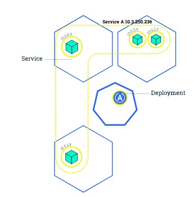
Figure 12 Rolling Update Initial State
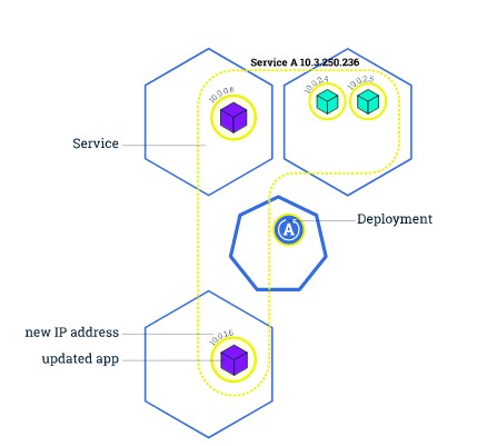
Figure 13 Rolling Update In progress deployment
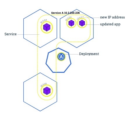
Figure 14 Rolling Update deployment: Finish
4. Security
Security is managed from the overall security & compliancy service on many different levels and within the scope of all architecture components and management services. The technical security foundation is created in the connectivity components with proper zone separation, firewalls, tunneling and attack-surface minimization.
AWS is responsible for protecting the infrastructure that runs AWS services in the AWS Cloud. For Amazon EKS, AWS is responsible for the Kubernetes control plane, which includes the control plane nodes and etcd database.
Following measures are suggested to ensure security in Cloud Architecture :
- Proper configuration of security groups that allow traffic to pass from the Amazon EKS control plane into the customer VPC
- Security patch updates of the host OS of EKS Cluster nodes
- Setting up and managing network controls, such as firewall rules
- Managing platform-level identity and access management, either with or in addition to IAM
- User requests must be signed by using an access key ID and a secret access key that is associated with an IAM principal. Or you can use the AWS Security Token Service (AWS STS) to generate temporary security credentials to sign requests.
- A setup of atleast 2 private and public subnets should be used so Kubernetes can create public load balancers in the public subnets that load balance traffic to pods running on worker nodes that are in private subnets.
4.1 Key Management
KMS: Cloud native Key Management Services (KMS) are a managed service that makes it easy to create and control the encryption keys used to encrypt data and protect the security of the keys. KMS keys will be used to encrypt the RDS.
Parameter Store: AWS Parameter store is used to store sensitive and critical information for configuration data management of the entire environment. To manage sensitive data, Secure String parameters will be created.
| Design Decision(s) | |
|---|---|
| DD-KM-25 | AWS Parameter store is used to store sensitive information as secure string parameters (works in conjunction with KMS). |
| Rationale | This ensure that the sensitive plaintext parameters are stored as encrypted parameters and decrypted when consumed in the automated pipeline by same or different AWS Account. |
| DD-KM-26 | Default Customer Managed Keys (CMK) will be used for Parameter Store. |
| Rationale | This ensures that the CMKs are rotated regularly by AWS. |
4.2 Certificate Management
AWS Certificate Manager is a service will be used which will allow to provision, manage, and deploy public and private Secure Sockets Layer/Transport Layer Security (SSL/TLS) certificates for use with AWS services and your internal connected resources. SSL/TLS certificates are used to secure network communications and establish the identity of websites over the Internet as well as resources on private networks.
| Design Decision(s) | |
|---|---|
| DD-CM-27 | All public CA signed-certificates must be renewed at least yearly. |
| Rationale | A pre-emptive measure to prevent any certificate leakage and abuse in the long run. |
4.3 Encryption
Encryption ensures data at rest and data in transit is secure and shielded from possible snooping or man-in-the-middle attacks. The following design decisions have been made within the context of the Target Architecture Design but also applies to As-is and Transition Architecture.
| Design Decision(s) | |
|---|---|
| DD-EC-28 | Data at rest encrypted with minimal AES256 with a key of 1024 (preferred 2048). (Follow the ENISA Standard) |
| Rationale | Lower encryption standards are no longer considered secure. |
| DD-EC-29 | Data in transit must be encrypted based on HTTPS. |
| Rationale | To ensure end-to-end security, all data transports must be encrypted based on standard internet protocols. If traffic is natively not encrypted (https based) then IPsec encryption should be applied on traffic. |
| DD-EC-30 | All data in transit should be encrypted with SSL/TLS. The preferred standard is TLS 1.2, and SSL is not allowed in any case. |
| Rationale | TLS is strongly preferred, but exceptions can be made for legacy environments to use SSL3. A waiver is required in that case. For Service to Service connections, encryption using certificates or keys are used when feasible and required. |
5. Compliance and Governance
5.1 AWS Config
AWS Config Rules allow you to codify policies and best practices for your organization and evaluate configuration changes to AWS resources against these policies.
Following rules are recommended to start with:
- Cloudtrail enabled.
- Root account MFA enabled.
- EBS storage encrypted.
5.2 AWS Trusted Advisor
AWS Trusted Advisor provides best practices in four categories: cost optimization, security, fault tolerance, and performance improvement.Trusted Advisor checks can be used to monitor and improve the deployment of Amazon EKS Cluster,ECR, Elastic Load Balancing, Amazon EBS, Auto Scaling, AWS Identity and Access Management, and other services.
5.3 Cost Control
Metering cloud consumption, understanding spend and optimising costs can be a daunting task given the complexity associated with the number of metrics (cost drivers) and always scaling environments.
Key business drivers include:
- Understanding the total spend and cost drivers associated with cloud services
- Visibility into the usage of individual services to understand and further analyze demand.
6. Roadmap
- Creating design patterns container based application deployment (EKS Cluster, ECR etc)
- Creating design patterns for CICD pipelines
- Design Infra modules to deploy
- Implement the design
7. References
https://d1.awsstatic.com/whitepapers/architecture/AWS_Well-Architected_Framework.pdf
https://d1.awsstatic.com/whitepapers/architecture/AWS-Security-Pillar.pdf
https://docs.aws.amazon.com/IAM/latest/UserGuide/best-practices.html
https://docs.aws.amazon.com/eks/latest/userguidehttps://docs.aws.amazon.com/config/latest/developerguide/managed-rules-by-aws-config.html
https://docs.aws.amazon.com/guardduty/latest/ug/what-is-guardduty.html
https://aws.amazon.com/blogs/mt/aws-config-best-practices/
8. Appendices
| AWS | Amazon Web Services |
| ACL | Access Control List |
| AZ | Availability Zone |
| ASG | Auto Scaling Group |
| LC | Launch Config |
| AES | Advanced Encryption System |
| AD | AWS Directory Service for Managed Microsoft Active Directory |
| MgAD | AWS Directory Service for Managed Microsoft Active Directory |
| ADFS | Active Directory Federation Service |
| CDN | Content Delivery Network |
| CLI | Command Line Interface |
| CIDR | Classless Inter-Domain Routing |
| CI/CD | Continuous Integration/Continuous Deployment |
| DMS | Database Migration Service |
| DNS | Domain Name System |
| DDoS | Distributed Denial of Service |
| DoS | Denial of Service |
| EC2 | Elastic Compute Cloud |
| EKS | Elastic Kubernetes Service |
| ECR | Elastic Container Registry |
| EBS | Elastic Block Store |
| ALB | Application Load Balancer |
| ELB | Elastic Load Balancer |
| EIP | Elastic IP |
| ENI | Elastic Network Interface |
| HTTP | Hypertext Transfer Protocol |
| HTTPS | HTTP Secure |
| IAM | Identity & Access Management |
| IGW | Internet Gateway |
| CMP | Internet Control Message Protocol |
| IP | Internet Protocol |
| IaaS | Infrastructure-as-a-Service |
| JSON | JavaScript Object Notation |
| KMS | Key Management Service |
| CMK | Customer Managed Key |
| MFA | Multi-Factor Authentication |
| NFS | Network File System |
| NS | Name Server |
| NAT | Network Address Translation |
| RDS | Relational Database Service |
| S3 | Simple Storage Service |
| SSL | Secure Socket Layer |
| SSE | Server Side Encryption |
| SDK | Software Development Kit |
| SSH | Secure Shell |
| SOAP | Simple Object Access Protocol |
| SSO | Single Sign-On |
| SAML | Security Assertion Mark-up Language |
| SaaS | Software-as-a-Service |
| STS | Security Token Service |
| TTL | Time To Live |
| TLS | Transport Layer Security |
| VPC | Virtual Private Cloud |
| VM | Virtual Machine / EC2 |
| WAF | Web Application Firewall |
| Fargate | AWS ECS Fargate |
| SG | Security Group |
| NACL | Network Access Control List |
| RDS | Relational Database Service |